

You can practice a Modbus TCP read–write–read sequence on one computer using Modbus Master and Modbus Slave in Aelrox. The slave provides a simulated register bank; the master connects to it and issues requests.
This walkthrough uses the loopback address 127.0.0.1 and port 1502. It does not require a PLC, a serial adapter, or access to another machine. The Windows screenshots show a real local session: an initial read of 0, a confirmed write of 1234, and a second read returning 1234.
Open both applications
Install Aelrox, then open these two application pages and choose Open in Aelrox for each:
- Modbus Slave, which supplies the simulated data.
- Modbus Master, which sends the requests.
Keep both windows available. This guide describes Master 0.3.0 and Slave 0.2.0. Select TCP in both; the RTU controls are for a different transport and are not used in this exercise.
Start the local slave
In Modbus Slave, use these settings:
| Field | Value |
|---|---|
| Transport | TCP |
| Listen address | 127.0.0.1 |
| TCP port | 1502 |
| Unit ID policy | Only configured Unit ID |
| Unit ID | 1 |
| Response delay | 0 ms |
Choose Start server and follow the request to allow the local listener. Continue when the interface reports that the server has started.
The listener and an outgoing connection require different access choices. Keep the listener on 127.0.0.1 for this exercise so the intended client is on the same computer. Do not replace it with a wildcard address.
If port 1502 is already occupied, choose another unused local port and use that same number in the master. A different port on each side will not form a connection.
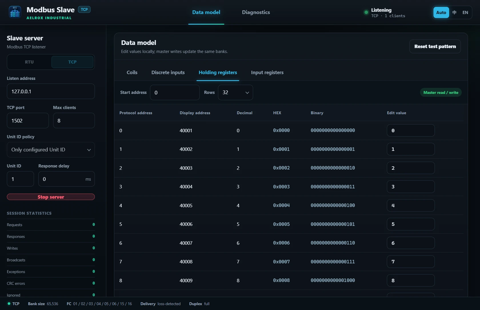
The Windows slave is listening on 127.0.0.1:1502 with Only configured Unit ID and unit 1. This screenshot was taken after the local master connected.
Connect the master
In Modbus Master, select TCP, enter 127.0.0.1 as Device IP, and change TCP port to 1502. The master's default port is 502, so check this field explicitly.
Choose Connect. Once connected, use Single operation for the following requests. Keep Unit ID at 1 so it matches the strict unit policy selected in the slave.
Read one holding register
Configure the first request as follows:
| Field | Value |
|---|---|
| Function | FC03 · Read Holding Registers |
| Unit ID | 1 |
| Protocol offset | 0 |
| Quantity | 1 |
| Data type | UInt16 |
Choose Execute and record the raw value returned for offset 0. That is your starting value; use the response from your own session rather than assuming the register has not been edited before.
Protocol offset and display address are different fields. In this interface, the first holding register uses offset 0 and can be displayed as 40001. Enter 0 in Protocol offset, not 40001, for this exercise. Keep that same offset for the write and the second read.
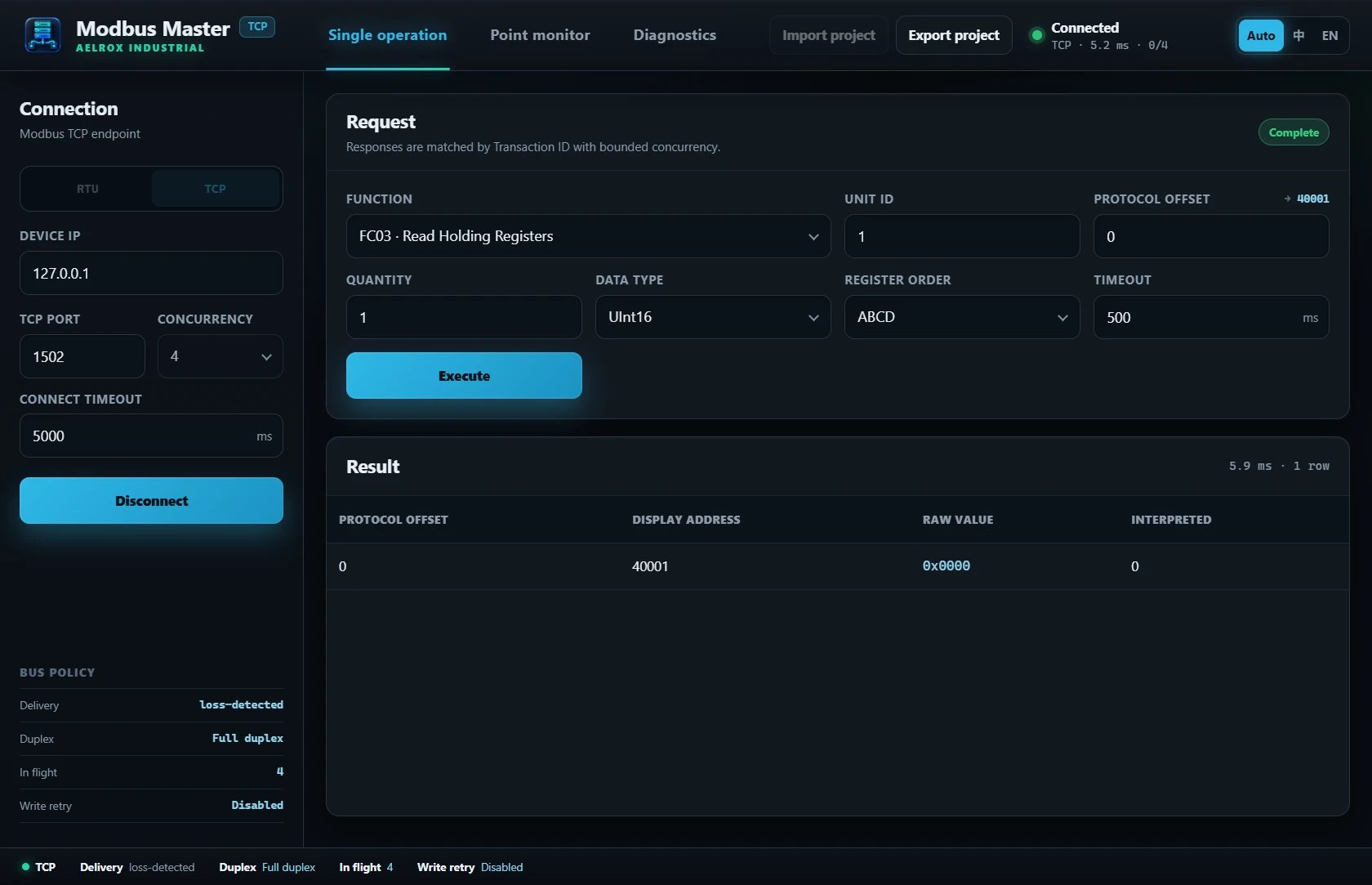
The first FC03 read in this session returned raw 0x0000 and interpreted value 0 at protocol offset 0, displayed as 40001.
Write one value, then read it back
Change Function to FC06 · Write Single Register. Leave the unit ID and protocol offset unchanged. Enter 1234 in Value and choose Execute.
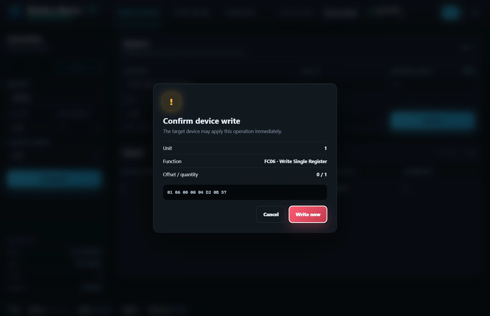
The real write-confirmation dialog for this local simulation. Check the unit, function, offset, and payload, then select Write now to send the write.
A successful write response is useful, but the next read is the check that completes the exercise. Switch back to FC03 · Read Holding Registers, with quantity 1, and execute it again.
For this exercise to pass, the raw value at offset 0 should now be 1234. If it is not, compare the unit ID, register type, and offset used in all three requests. A holding register and an input register are separate data areas even if their offsets are the same.
Keep a simple record:
| Check | What to record |
|---|---|
| First FC03 read | Your starting value at holding-register offset 0 |
| FC06 write | The response to writing decimal 1234 |
| Second FC03 read | Whether the same location now returns 1234 |
This confirms a particular local exchange. It does not certify a physical device, a production network, or every function supported by either tool.
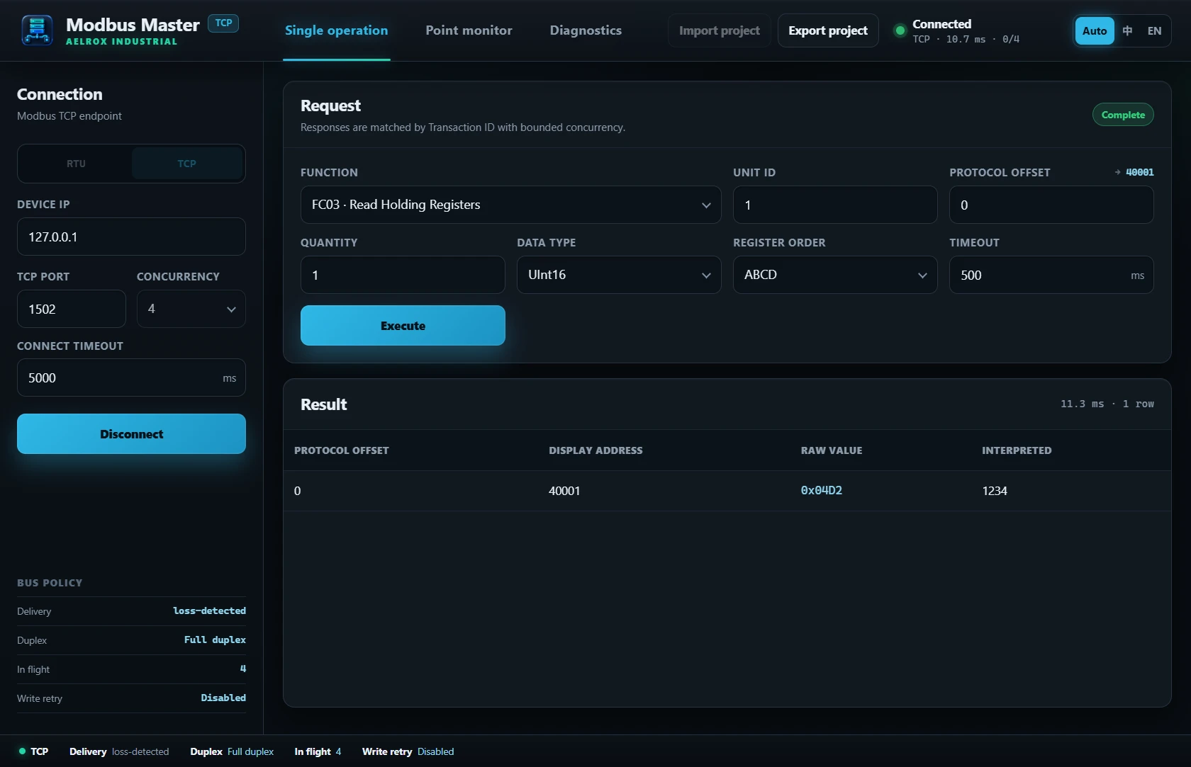
After confirming the FC06 write, the second FC03 read returned raw 0x04D2 and interpreted value 1234. This verifies this local read–write–read exchange, not a physical PLC or production network.
Troubleshoot one layer at a time
If the master cannot connect, check that the slave is running and that both host and port match. The default-port difference between 502 and 1502 is an easy detail to miss.
If it connects but the request fails, check the unit ID, function, offset, and quantity. Use the diagnostics views to inspect the reported problem before changing several settings together.
If a read returns an unexpected number, compare the raw UInt16 value first. Multi-register types and byte ordering add another interpretation layer; leave them for a later exercise once the single-register sequence works.
Stop the exercise
Disconnect the master, then stop the slave server. Keep your settings and response notes if you want to repeat the sequence.
Open Modbus Slave and Modbus Master to try the local register exercise. If your task instead involves raw serial messages, see sending text and HEX data with Serial Debug Studio.